Wave: Pan-Tipping Assistant
Accessible cooking for individuals with limited hand strength or wrist mobility.
01 | Overview
Revolutionizing Cooking with Effortless Control
ME103: Design and Making is a mechanical engineering course at Stanford where students design and manufacture a product of their choice. It involves sketches, rapid prototypes, CAD designs, manufactured test models, and ultimately, a customer-ready prototype. In this course, I created Wave, a pan-tipping assistant designed to make tilting a pan effortless, much like riding a wave.
Product Designer
April - June 2022
6 weeks
Patternmaking, Casting, Milling, Woodworking, Finishing
Aluminum 356
Thermal Oak Wood
Threaded Brass Inserts
Stainless Steel Machine Screws
Design Sketching, CAD Modeling, Rapid Prototyping, 3D Printing, Manufacturing
02 | Problem
Pans are Heavy!
Growing up, I always loved watching my mom cook because I got to witness firsthand the pure joy that it brought her. She would always find new recipes online to try out and then proudly show off her creations to my brother and me. However, with age, she experiences increased wrist strain that makes it challenging to hold her favorite wok, especially in one hand while the other hand is serving the food.
My solution was to design and manufacture a stand that she could rest her pan of food on, relieving the stress placed on the wrist and thus making cooking more accessible to those with limited hand strength or wrist mobility.
CAD Modeling
- Sketched with spline tool on Fusion 360
- Extruded sketch 0.375” (half of desired width)
- Filleted and drafted all angles by 5° to get easier pull when casting
- Mirrored entire body over yz-plane to get entire part
Consists of wooden base and two critical parts. Critical parts are fastened to ends of base.
Patternmaking
- 3D printed half of critical part twice with polylactic acid (PLA), resulting in two mirrored parts
- 3D printing double-sided pattern would ensure consistency among the two parts, especially since the shape was so organic
- Included two holes for easy alignment when attaching to the patternboard
- Used drill and table cutter to create board out of 1” “no void” plywood
- Positioned pattern on one side and marked where to drill alignment holes
- Inserted 3/16” dowel through holes to secure other half of pattern onto other side of the board
- Cut out general shape of gate & runner with bandsaw from 1” thick scrap wood
- Drafted gate & runner with disc sander, spindle sander, and sandpaper at 10° angle
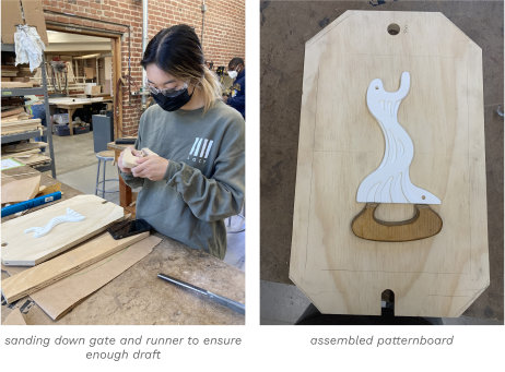
- Sanded and sealed everything with shellac to fill pores in the wood and pattern
Post-Machining
To smooth the casted parts’ surfaces, I used a strap clamp setup with angle blocks to secure the casted part to the mill. I then used a shell mill tool to face off the front and back faces of the part and repositioned the clamps in between to face off the areas initially covered by the clamps.
Since the casted parts would be fastened to a base, I needed to smooth out the bottom of the stands as well. To do this, I used a level tool and the right angle block clamp setup to ensure the part was straight and then used the shell mill tool to face the bottom.
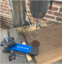
The stands would be secured to the base with fasteners, so I drilled two holes into the bottom of each part and tapped threads for 10-24 machine screws.
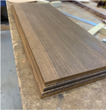
Woodworking
Used 0.75” thick thermal oak wood to make the base. Cut down to size with the table saw so that there was a 0.5” margin. Then used router to cut out nice design along edges.
Marked where casted parts would stand on base according to the holes in my parts. Drilled corresponding holes into the base and used countersinking tool to countersink each hole and have machine screw flushed with the wood. Then screwed in threaded inserts to fasten the machine screws.
06 | Reflection
Key Takeaways
This was the first opportunity I had to design and manufacture a product of my own. Having come into the class with no prior experience in manufacturing, I was intimidated by the amount of knowledge and skill I would have to pick up, but as I spent more time in the lab, I was able to learn how to weld, machine, cast, and woodwork, becoming more comfortable with the various tools, machines, and manufacturing processes.
I also learned the importance of iteration and troubleshooting. Failure was inevitable during this process, but working through these challenges provided me constant opportunities to discover, problem solve, and brainstorm various solutions. This project has left me with a valuable set of personal skills and an impressive knowledge of new manufacturing and design techniques.
.png)


